Air Quality Meter - Step 1: the Display
Sep 05, 2020
This is the start of a new project that I'm figuring out as I go. My end goal is to build a handheld air quality meter built off a Raspberry Pi, but there are plenty of steps between here and there that I'll have to get through first.
Background
As a bit of background, I have pretty bad asthma, that's been getting worse every year do to California's worrying trend of having terrible, multi-week forest fires every year now. "Fire season" has always been a familiar phrase here, but growing up, it was more of a threat, and less a promise. I recommend reading about how indigenous peoples in California, including Yurok, Karuk, Hupa, Miwok, Chumash tribes, have a tradition of using controlled burns that managed the fires and fostered the beautiful forests here, before California outlawed the practice because colonialism.
Anyway, I've become fairly reliant on the PurpleAir website, where people can buy a fairly affordable (\$230 - but this kind of thing used to cost way more) wifi-connected air quality meter that gets shared out to a map, which shares real-time air quality that often shares results that are within a couple blocks from you if a neighbor decided to buy a device. However, that's not enough for me. I want to be able to wave around a handheld meter like a ghost hunter on TV, divining whether the air outside my apartment is safe, or whether my windows are leaking smoke. So, that's where we're kicking off.
Building the display
Parts:
- 16x2 LCD Display
- Specifically the OSEPP-LCD-01 keypad shield.
- Arduino Uno R3
This decision was based on the fact that I had a 16x2 display already lying around, and that I wanted to keep my GPIO pins free for the other parts I'm going to use for this project.
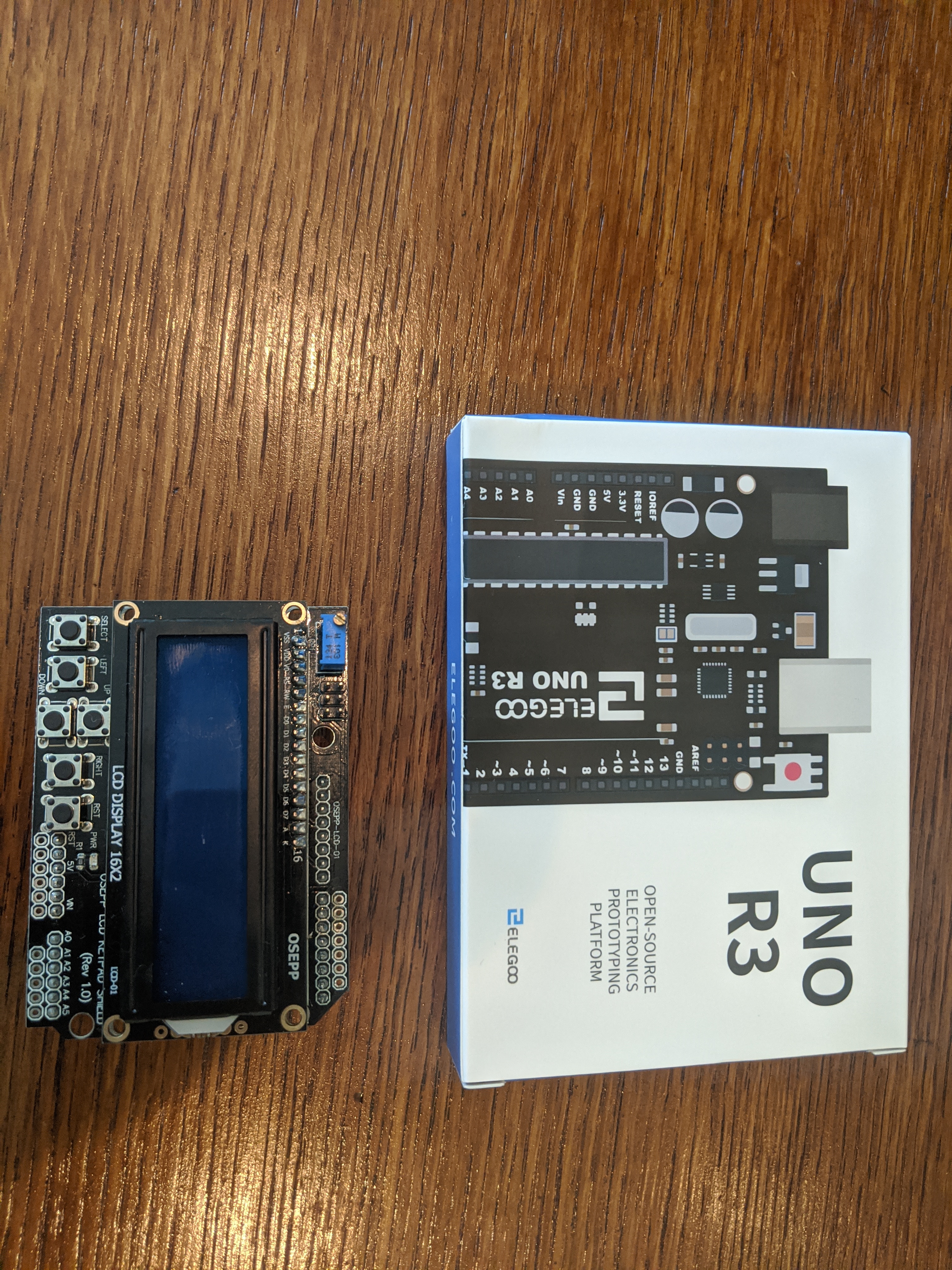 Parts for the Display
Note - this display is a relatively old model, and it isn't important to use the exact model. You may have to look up a different set of Arduino drivers from the manufacturer if you are building this project on your own.
Getting started
Assembly is blessedly simple, this time. The keypad/display shield is designed to fit an Arduino, so you can just insert the pins and get rolling.
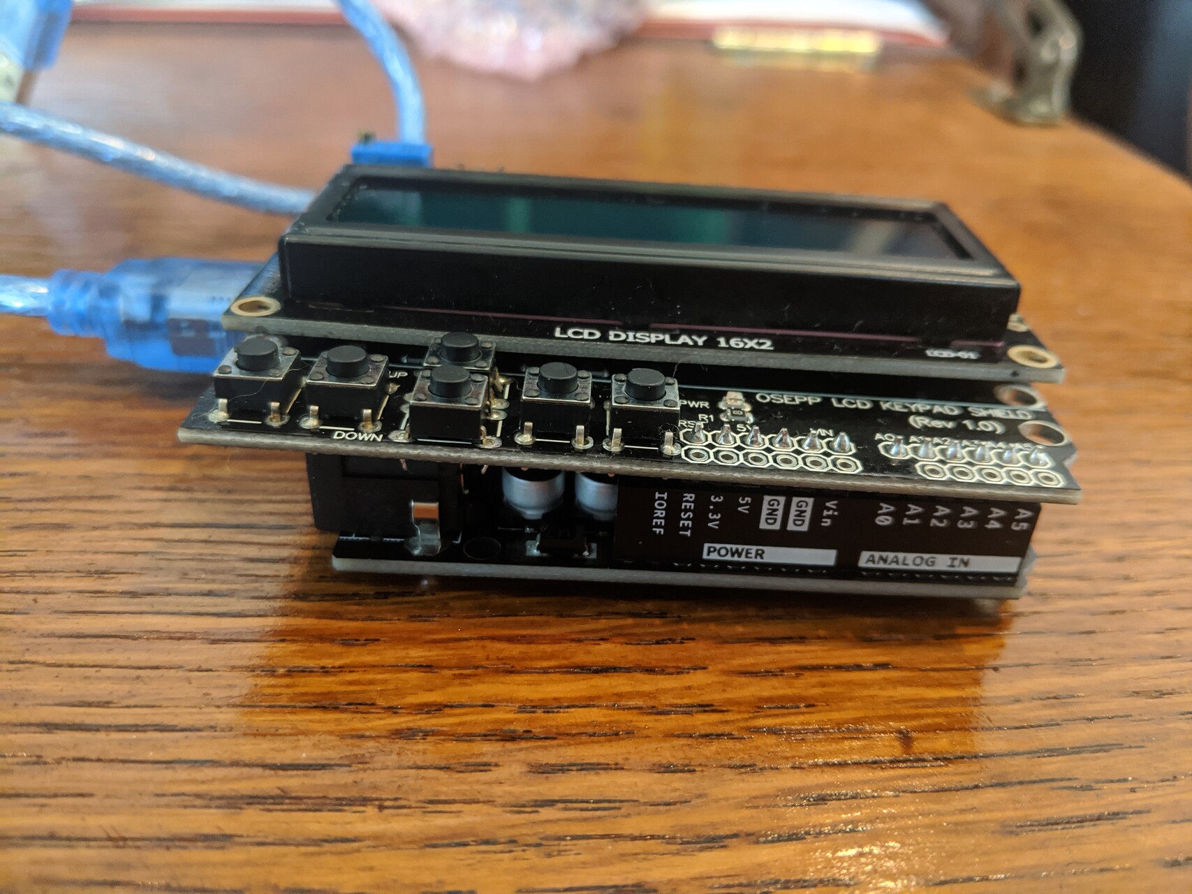 Just stick 'em together
Now, if you plug the USB cable into your PC, you'll see the display receive power, but it's not going to be functional yet.
I don't currently have the Arduino IDE, so I grabbed it from their Downloads page
I also grabbed the Sample Code from the OSEPP website for my display.
I dropped the buttontest code in, and it worked with no problems!
So, that solves the generic issue of "write to the screen", but the rest of this application is going to be written in Python, running on the Raspberry Pi to take advantage of the drivers that the lovely folks at Adafruit have written.
Therefore, I'll need to set the code up to allow me to communicate back and forth between the Arduino and the Python script, sending messages to be displayed, and passing button inputs from the board back to Python.
Coding for the display
Step 1 - Hello World
I've started by modifying the buttontest script to accept input and output from Serial. Here's the code to receive a message:
// serial_lcd.pde

#include <LiquidCrystal.h>
LiquidCrystal lcd(8, 9, 4, 5, 6, 7);

String inputString = "";

void setup()
{
lcd.begin(16, 2);
Serial.begin(9600);
inputString.reserve(200);
lcd.setCursor(0,0);
}

void serialEvent()
{
  while (Serial.available()) {
    lcd.clear();
    inputString = '\0';
    // wait a bit for the entire message to arrive
    delay(100);
    while (Serial.available() > 0) {
      // display each character to the LCD
      char inChar = (char)Serial.read();
      inputString += inChar;
    }
    for(auto x : inputString)
    {
      if(x == '\n'){
        lcd.setCursor(0,1);
      }
      else {
        lcd.write(x);
      }
    }
  }
}
So, let's break down what's happening here:
- I'm setting up the LCD display using the LiquidCrystal drivers, and assigning it to the pins that are currently wired to the display.
- Then, I declare a buffer string for any serial messages that come in.
- Next, I'm setting up the display, opening up a Serial connection, and setting the cursor.
Next, the serialEvent is set up to listen to any messages coming in over the USB connection. It resets the screen and my string buffer, and then concatenates the whole message into a string. I then iterate through the characters and write them to the display, with bonus logic to handle a newline character to write to the second row.
Next, the Python code:
# Arduino.py

import serial
import time
import io

arduino = serial.Serial('/dev/cu.usbmodem14201', 9600,
                        timeout=0, parity=serial.PARITY_EVEN, rtscts=1)
sio = io.TextIOWrapper(io.BufferedRWPair(arduino, arduino))
# The sleep is important to let the arduino wake up!
time.sleep(2)

sio.write('Hello World');
sio.flush()
Not so bad, right?
Here we set up the serial port, targeted at the port my Arduino is using, and use the io wrapper to support sending simple strings.
After that, all we have to do is write our string and flush the serial io to send our message along!
Sending messages back
Since we have a bunch of convenient buttons already attached, I naturally want to be able to use them to send messages back to the main application.
The buttontest example gives us a good head start on this boilerplate, but I modified to change the logic to only send a message out on Serial when the most recent message changes. That looks a bit like this:
// serial_lcd.pde

int last_message = 0;
int lcd_key     = 0;
int adc_key_in  = 0;
int current_line = 0;
String inputString = "";         // a String to hold incoming data
bool stringComplete = false;  // whether the string is complete
#define btnRIGHT  0
#define btnUP     1
#define btnDOWN   2
#define btnLEFT   3
#define btnSELECT 4
#define btnNONE   5

// read the buttons
int read_LCD_buttons()
{
 adc_key_in = analogRead(0);      // read the value from the sensor
 // my buttons when read are centered at these valies: 0, 144, 329, 504, 741
 // we add approx 50 to those values and check to see if we are close
 if (adc_key_in > 1000) return btnNONE; // We make this the 1st option for speed reasons since it will be the most likely result
 if (adc_key_in < 50)   return btnRIGHT;
 if (adc_key_in < 195)  return btnUP;
 if (adc_key_in < 380)  return btnDOWN;
 if (adc_key_in < 555)  return btnLEFT;
 if (adc_key_in < 790)  return btnSELECT;
 return btnNONE;  // when all others fail, return this...
}
void loop()
{
  lcd_key = read_LCD_buttons();
  if(lcd_key != last_message){
   last_message = lcd_key;
   Serial.print(lcd_key);
  }
}
Now we are sending data back over serial as codes ranging from 0-5.
We can program python to listen to these messages with this code:
# Arduino.py

last_code = ''


def handle_button(code):
    global last_code
    if code == last_code:
        return
    last_code = code
    switcher = {
        '0': 'RIGHT',
        '1': 'UP',
        '2': 'DOWN',
        '3': 'LEFT',
        '4': 'SELECT',
    }

    msg = switcher.get(code, 'NONE')
    sio.write(f'Button: {msg}')
    sio.flush()


while True:
    new_message = bytes(arduino.readline()).decode("utf-8", 'ignore')
    if(new_message != ''):
        handle_button(new_message)
    time.sleep(.1)
Now, we can press buttons on the LCD Shield, process those codes in Python, and respond by updating the screen with the code!
Since we can also pass new line characters, I can now predictably write to all the available spaces using two 16 character strings joined by a \n newline character.
I'm satisfied with this functionality for now, so stay tuned for part 2 where I'll wire up the air quality sensor!